

Rapid control prototyping
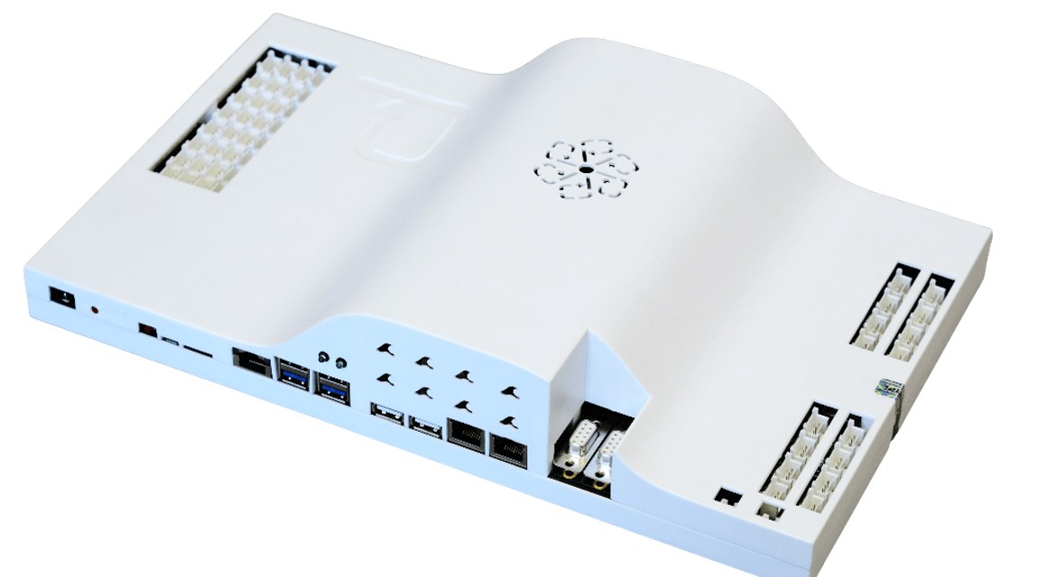
SmartRCP is a control platform that provides a breakthrough and robust solution for fast and efficient validation of power electronics converters. It allows a perfect balance between digital processing power and hardware interconnectivity to implement any control algorithm and apply it to any converter topology effortlessly.

High-end FPGA
Based on a Xilinx Kria K26 SoM
- Quad-core Arm® Cortex®-A53 MPCore™ up to 1.5 GHz
- Dual-core Arm Cortex-R5F MPCore up to 600 MHz
- 4 GB of DDR4 RAM
Fast design
Program the FPGA using HLS or directly in VHDL or Verilog and, at the same time, program the four available high-specs ARM microprocessors.
Detailed templates, tutorials and demo boards (buck converter) to get started.
Detailed connectivity
Connectivity specifically designed for the control of power electronics converters, including DAC, ADC, digital in/outs and other protocols like Ethernet, USB, or RS-485.

PWM modulation features are fully controlled as they are defined in C or VHDL.

The code validated by RCP can be exported directly into the real Control Unit.

Remote Controlling capabilities.

Embedded oscilloscope & datalogger and advanced post-processing tools.

In deep documentation and application examples provided

PSC Engineering & Consulting services available upon request.

Suitable for distributed control techniques.
What does SmartRCP include?
How SmartRCP is supplied
Rapid control prototyping (RCP)
ITEM 0 alone, or with ITEMS 1 and 2. The control runs on the SmartRCP and drives the real power converter.
SmartRCP
Hardware platform and demo
User interface, oscilloscope and buck converter demo.
IPs CTRL DC — 6 control blocks
Modulators, regulators, filter, RMS calculator and ramps.
Control IPs for AC
Takes the platform from DC to AC conversion.
IPs CTRL AC — 9 control blocks
SVPWM, classic NPC, ANPC, DPWM1 and DPWM1Max modulators.
PLL regulator, DQ transform, active / reactive power calculator and motor flux estimator.
Control Templates for Power Converters
Complete control stages, one per converter topology.
8 DC topologies
Synchronous buck, DAB (SPS, TPS and 3-phase), 3-phase boost inverter-rectifier with 3 or 4 legs, Alhambra and full bridge.
6 AC topologies
Vienna rectifier, boost and totem-pole PFC, buck rectifier and motor drive.
Real-time simulation (RTS)
ITEM 0 with ITEM 3. The power converter is simulated inside the SmartRCP.
RTS Models
The converter and its electrical environment, simulated in real time inside the SmartRCP.
Converter models
DAB, synchronous buck, 3-phase boost inverter and Vienna rectifier plants.
Electric models — 7 models
Battery, solar panel, 3-phase grid, PMSM and induction motors, real MOSFET half-bridge and Foster thermal network.
Hardware
Signal chains and computing core.
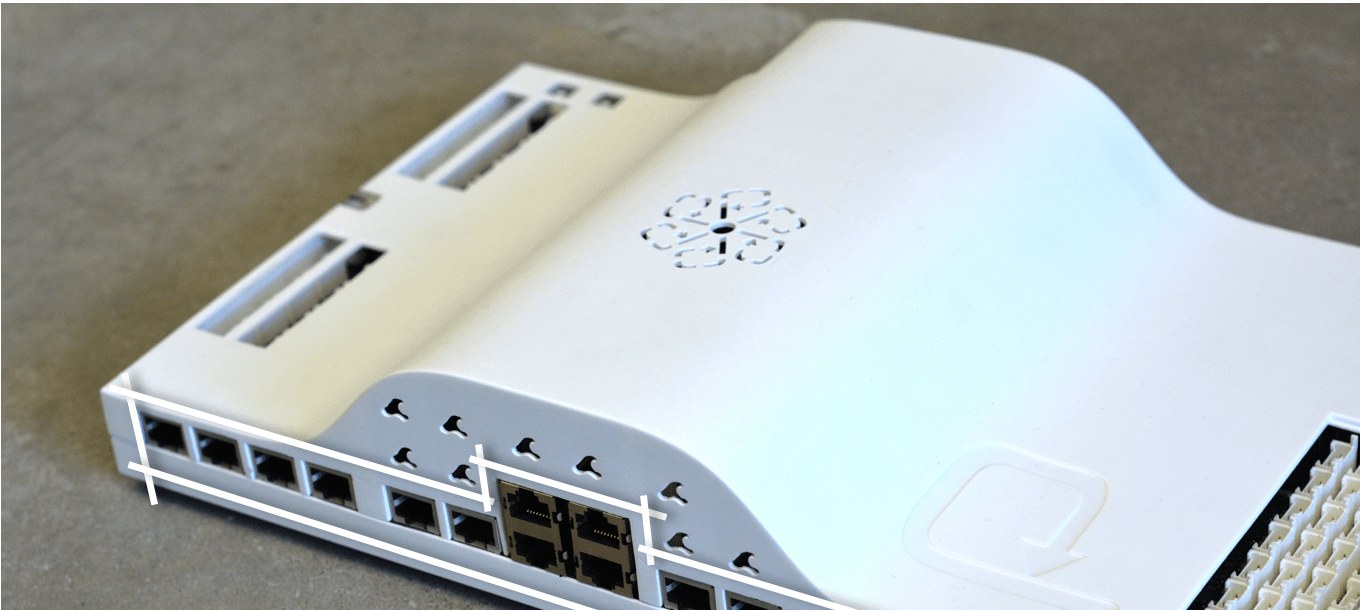
PWM Channel chains details
- PWM channels are fully electrically isolated.
- To reduce noise susceptibility, a differential RS-422 protocol is used, and all connectors are shielded.
- Additional enable and status/error signals are provided to interface driving circuitry.

Analog input chains details
- All input analog channels share analog chain topology and input span of 0–5 V.
- Antialiasing filters are tuned at 1.5 MHz for fast channels and 200 kHz for slow channels.
- Analog front end provides a differential input with selectable input impedance, low input current and high bandwidth.

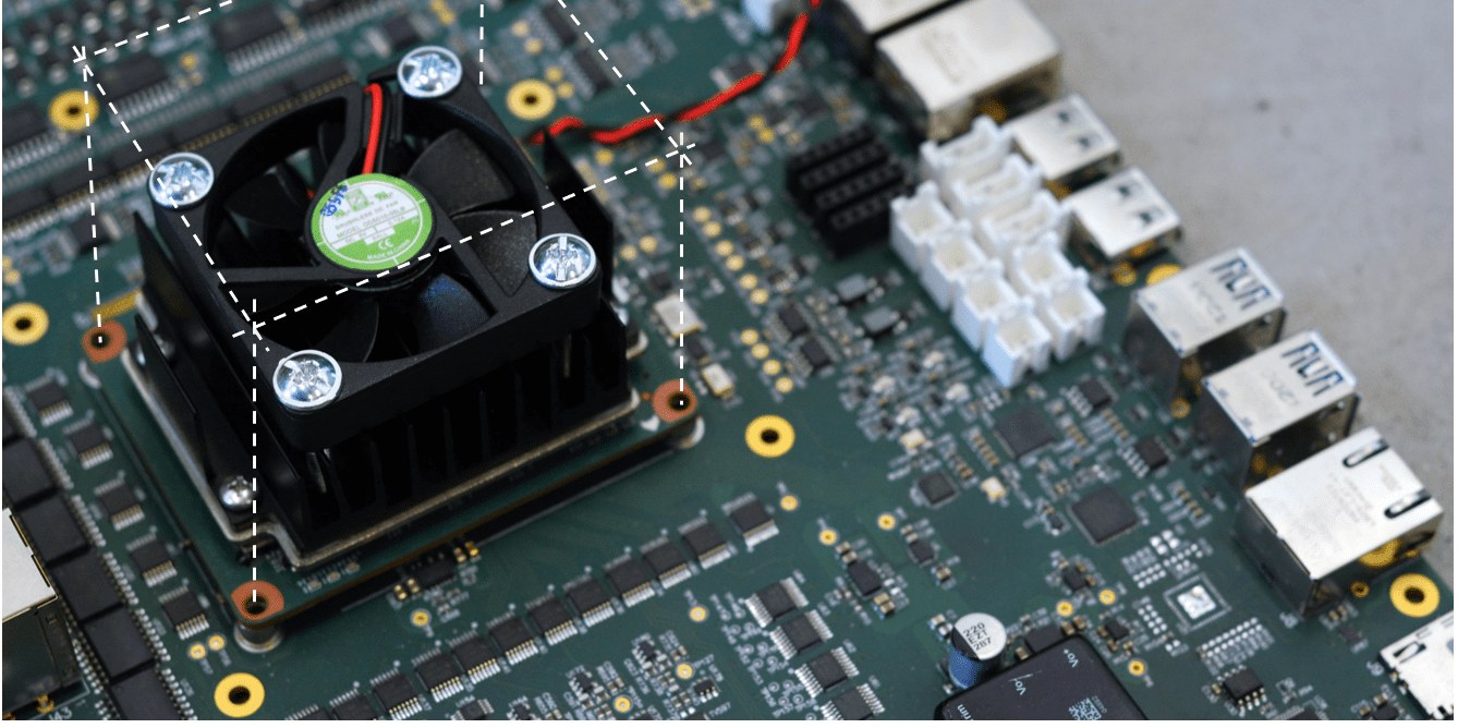
Computing core
The SmartRCP computing core is based on an AMD Kria K26 SOM. This platform allows the integration of a custom AMD Zynq UltraScale MPSoC build together with an embedded processing system. Thus, a robust and efficient compromise between microprocessor-based and FPGA programming is achieved, enabling the development of any power electronics control architecture with almost no limits.

Processing System (PS) specifications
- Quad-core Arm® Cortex®-A53 MPCore™ up to 1.5 GHz
- Dual-core Arm Cortex-R5F MPCore up to 600 MHz
- Mali™-400 MP2 up to 667 MHz
- 4GB 64-bit DDR4 (non-ECC) and 16 GB eMMC
Programmable Logic (PL) specifications
- 256k System Logic Cells
- 234k CLB Flip-Flops
- 117k CLB LUTs
- 144 BRAM
- 64 URAM
- 1248 DSP Slices
- 2 speed grade, low voltage and –40 to 100°C temperature range

SmartRCP Interface is the desktop application that connects to the SmartRCP platform and operates it remotely. From a single environment it configures the measurement chain, exchanges variables with the running control application, captures internal signals for analysis and reports the state of the system and its active protections.
Documentation and setup tools
The home page gathers the reference material in one place: the SmartRCP documentation, the Interface manual, a set of step-by-step Quick Start guides available in English, Spanish and Chinese, and the example videos. The configurations opened most recently are listed beside them.
Two bench utilities are included. A network scan reports the SmartRCP units that answer on the local network, together with their identity, MAC address and IP address. A guided form writes the uSD configuration file, so the network parameters and the identity of a unit do not have to be edited by hand.
Rapid system monitoring
The Overview page monitors the operation state of the SmartRCP, its active alarms, the measured signals and any other control variable, in a fully customizable way. Numeric readouts and history plots are presented together, so a value can be read at an instant and followed over time on the same page.
Which signals appear as numeric readouts, which ones are plotted, how the plots are distributed and how much history each one retains are defined by the user. The arrangement can be modified while the system is running, without interrupting the acquisition.
ADC Configuration
The 24 ADC channels available in SmartRCP are configured from a single page:
- Gain and offset of each channel.
- Upper and lower limit of each protection.
- Cut-off frequency of the low-pass filter of each channel.
- Name of each channel, and whether its instantaneous, RMS or average value is shown in Overview.
PL and PS registers
The registers carry values between the interface and the application running on the platform, so control changes — controller gains, switching frequency, dead time, and any other parameter of the design — are applied online, without rebuilding the user application for each test.
The interface provides 32 write registers and 32 read registers on the programmable logic side (PL), and 64 write registers on the processing system side (PS), available to the processor cores. Each register takes a name defined by the user and is interpreted as an integer or as a floating-point value.
Embedded Oscilloscope
The interface includes the Embedded Oscilloscope for the acquisition and analysis of the internal signals of the control: measured signals, control variables and register values.
- 6 simultaneous channels, 2500 samples per channel.
- Sample step configurable from 50 ns, the acquisition period of the platform.
- Single or continuous acquisition, with a configurable trigger level.
- Time-domain and frequency-domain representation, with a distributable plotting area.
- Zoom and cursors for time and amplitude measurements.
- Derived signals obtained from mathematical operations between channels, including FFT.
- Captures saved to file and loaded again for later analysis.
Alarms and protections
Each ADC channel has an upper and a lower protection limit, and a message can be defined for each of the two. When a protection trips, the interface identifies the channel involved and reports the event with that message, in the terms of the application rather than as a generic code.
The protection is rearmed from the interface itself once the cause has been examined. The event log keeps a timestamped record of every event.
Validate your power converter control on SmartRCP
Download the brochure, explore the resources or ask us for a quote.