SmartCtrl![]()
Control Design Software for Power Electronics
 Quick start and Documentation
Software News and Documentation
SmartCtrl 2025.1 What’s New

SmartCtrl 2024.1 What’s New

SmartCtrl 5.0 What’s New

SmartCtrl 4.2 What’s New

SmartCtrl 4.1 What’s New
PDF Tutorials
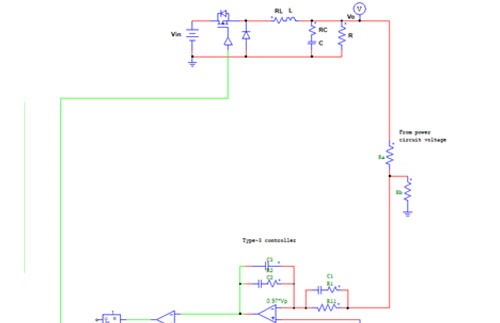
Single Control Loop Design
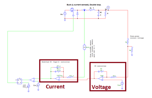
Double Loop Control Design
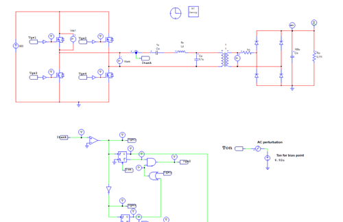
Resonant Converter Control Loop Design
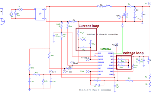
Boost PFC Converter Control Loop Design
3 Phase grid connected PV Inverter
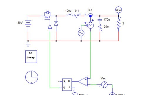
Peak current control with AC sweep model
Boost converter s domain model
Discretized digital control loop
Digital Control Double Loop Design
Peak current model
Single Phase Voltage Source Inverter
Designing a Digital Control in z-Domain

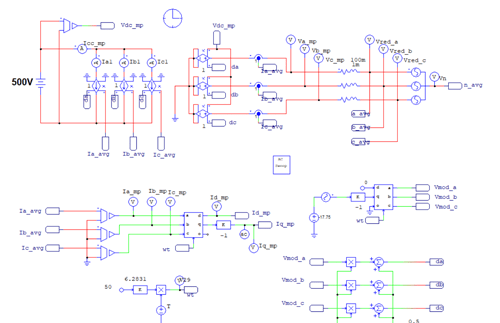
DQ control of Three Phase PFC Boost Converter

Design of control loops for a Permanent Magnet Synchronous Machine
SmartCtrl Past Webinars
Design of Control Loops for a Three-Phase Induction Motor
Digital Control of a Three-Phase Two-Level Power Factor Correction Rectifier
Design of control loops for the three-phase Vienna rectifier
Digital control of a three-phase inverter with LCL filter
Three-Phase Two-Level Power Factor Correction Rectifier 2025
1-phase voltage source inverter
Resonant Converter Control Loop Design
Two-Level Power Factor Correction Rectifier
Phase-Shifted Full-Bridge DC-DC converter
PSIM and SmartCtrl: Average current mode control of Buck converter
Digital Control of Buck converter
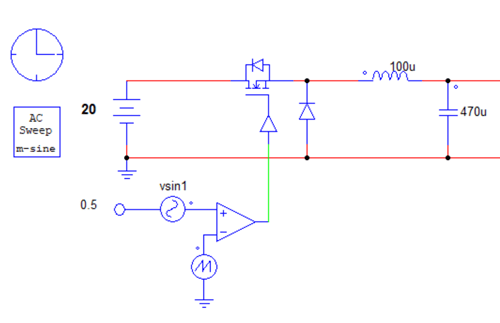
Peak Current Mode Control of Buck Converter
Power control of a three phase grid connected inverter
SmartCtrl Frequently Asked Questions
SmartCtrl is a design software that allows users to easily and efficiently adjust the control loops of most power converter topologies (DC-DC, AC-DC, DC-AC, AC-AC). SmartCtrl provides a perfect combination of predefined topologies and compensators, and capabilities for custom design with a powerful equation editor that allows users to create their own transfer functions for all the power converter elements: plant, sensor and compensator.
SmartCtrl is a versatile tool, allowing users to define the converter’s plant in different ways:

- The first design possibility is called “DC-DC power stage and control circuit design”. This option provides a full design, both in power stage and controlling system, from high level specifications like input and output voltages, power level and maximum ripple. This wizard provides a full solution which can be fully tuned or modified by user.

- The next option is known as “Predefined Topologies.” This group includes the main DC-DC converters, such as the buck converter, boost converter, buck-boost converter, flyback, forward, phase-shifted full-bridge, and dual-active-bridge.

Among the predefined topologies, there are also some AC-DC converters, such as the single-phase power factor corrector and the two-level three-phase power factor corrector.


- Another option is known as “Import frequency response data from .txt file.”
This option is particularly useful when designing control for an experimental prototype, since a frequency response analyzer (FRA) can be used to obtain the converter’s plant frequency response. The data obtained from the FRA can be saved in .txt format and imported into SmartCtrl.
Similarly, if a simulation template/schematic is available, any AC sweep tool provided by the simulation software can be used to obtain the converter’s frequency response, and the data can then be imported into SmartCtrl.

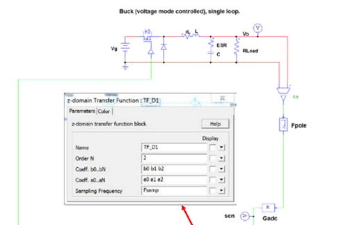
- Finally, the “Equation Editor” option can be found within SmartCtrl. This alternative allows the user to define the transfer function analytically. The transfer function can be defined either in the frequency domain or in the discrete domain.

For DC-DC converters, the following control structures can be selected:
- Single loop Voltage mode control or Single loop Current mode control.
- Peak current mode control.
- Average Current Mode Control or double loop control.
For the single-phase AC-DC converter, the following control structure can be selected:
- Average Current Mode Control or double loop control.
For three-phase AC-DC converters, the following control structures can be selected:
- Double loop control in the alpha-beta reference frame.
- Double loop control in the dq reference frame.
In order to ease the first attempt when designing a control loop, a map of the stable solutions space has been developed under the name of “Solution map”.
 |
 |
Based on the selected plant, sensor, and type of compensator, the “Solution map” provides a “safe operating area” of the different combinations of crossover frequency (fcross) and Phase Margin (PM) that lead to stable systems. The parameters involved are represented as PM vs Cross Frequency, and users can select different points from the “Solution map” to see the impact on the rest of design variables and graphs in real time within SmartCtrl.
With the “Equation Editor” option, users can design generic control structures with a single loop, double loop, triple loop, etc.
The main advantage of a generic control structure is that the controlled variable can be of any kind. For example, in the case of electric motor control, SmartCtrl allows designing the loops that control the motor’s torque, speed, and position.
SmartCtrl includes certain predefined compensators, such as:
- Type 2
- Type 3
- Proportional-Integral (PI)
- Unattenuated PI
- PI analog
- Single pole (for PFC)
- Proportional-Resonant (PR)
Additionally, compensators can also be defined using the Equation Editor, allowing users to fine-tune their own compensators.
SmartCtrl allows the design of both analog and digital control loops.
For digital control, SmartCtrl considers digital delays, ADC gain, and DPWM gains. As a result of the design, SmartCtrl calculates the values of the equation coefficients that users would implement in a FPGA or DSP.
SmartCtrl allows to design an analog control loop and discretizing it, and also to create the control loop directly in digital. In addition, SmartCtrl allows to design the control loop in discrete domain (Z variable).
Yes. By means of the Equation Editor, users can introduce the motor plant and design its controller.
Yes. By means of the Equation Editor, users can design single loop or double loop controllers.
Yes. Users can export the transfer functions to .txt, .csv or .xls.
Yes. Users can modify every device or add new ones.
Yes. Users can load the system transfer functions obtained from a third-party software or a measuring device, like an impedance analyzer, as they are imported as data files into SmartCtrl.

Yes. With the parametric sweep option, users can sweep every value to assess its impact on the design in real time.
 |
 |
Yes, SmartCtrl is fully capable to design the control stage of cascaded converters. In fact, SmartCtrl provides the close loop impedance of the converters to analyse the interaction and assure its stability.
The SmartCtrl installation guide can be found in the following link: SmartCtrl-Installation-Guide.pdf (powersmartcontrol.com).
Fill in the form Form_trial – Power Smart Control, and the trial request process will be initiated (requests will be processed as soon as possible).
The design results can be directly exported from SmartCtrl to third-party simulators.
Currently, they can be exported to simulation software such as PSIM and SIMBA directly and automatically from SmartCtrl. In any case, the results obtained from SmartCtrl can be easily extracted and implemented in any simulation tool manually.
PDF tutorials of SmartCtrl can be found at Power Smart Control S.L. website, in the following link: SmartCtrl Resources – Power Smart Control
Videos and recorded webinars of SmartCtrl can be found at Power Smart Control S.L. YouTube Channel, in the following links:
Write an email to support@powersmartcontrol.com for technical issues or to sales@powersmartcontrol.com for commercial issues.
Yes. Users will receive a notification inside the application for any new update.
Sample layouts and Sample design tutorials for SmartCtrl
Boost converter double loop I_diode feedback_layouts
Boost converter double loop I_inductor feedback_layouts
Boost converter single loop I_diode feedback_layouts
Boost converter double loop I_diode feedback_design tutorials
Boost converter double loop I_inductor feedback_design tutorials
Other external tutorials
How to Use SmartCtrl
for Predefined Converter Topologies
Buck inner current loop design with SmartCtrl & PSIM – general method
Using SmartCtrl to design the outer voltage loop of a Buck
Boost PFC – Complete design and AC analysis
Digital Controller Design with PSIM – Digital Delay effects
How to Implement Field Oriented Control of a PMSM with PSIM and SmartCtrl
Getting Started with General Control System Design with SmartCtrl’s Equation Editor