![]()
Magnetic design tool for experts and non-experts.
 Downloads and resources
PDF Tutorials
Database Editing
Inductor Design Example
Transformer Analysis
Transformer Design Example

Inductor Analysis and Optimization
SmartNetics Past Webinars
Transformer Analysis with SmartNetics
Presenting SmartNetics: Our approach to magnetic design
Transformer design with SmartNetics
Inductor analysis and optimization
SmartNetics Frequently Asked Questions
General questions
SmartNetics is a new approach to the design and optimization of magnetic components, aimed for the expert engineer as well as for a newcomer to the magnetic design. It offers a range of features tailored to meet the needs of the electronics industry.
Unlike other commercial software, SmartNetics does not provide a single black-box solution. Instead, it provides the user with every design that meets their needs, allowing them to select the one that is best suited for every particular application, regardless of whether the focus is on performance, volume, cost or any possible combination of parameters.
Key Features of SmartNetics:
- Waveform Input: Supports sinusoidal, triangular, and rectangular waveforms, as well as custom inputs from .csv files.
- Geometries: Includes core configurations with EE shapes, utilizing E or parallel U
- Winding Strategies: Offers concentric winding configurations on the center
- Gapping strategies: Supports standard gapping (same gap in every leg), single gap in the central leg or distributed gaps in the central
- Device Types: Design and analyze single-phase inductors and single-phase transformers with a single secondary.
- Customizable Databases: Manage and edit databases from external
- Accurate Thermal Modelling: Simulates dissipation by natural
- Device Comparison and Selection: Graphically compare and filter designs across up to eight parameters simultaneously.
- Integration with Third-Party Tools: Easily export designs to advanced simulation software like Ansys Maxwell and Altair Flux for finite element
- Professional Report Generation: Export comprehensive design and analysis reports in PDF format, facilitating documentation and communication with manufacturers.
The typical workflow consists of five steps, as shown in the next figure:
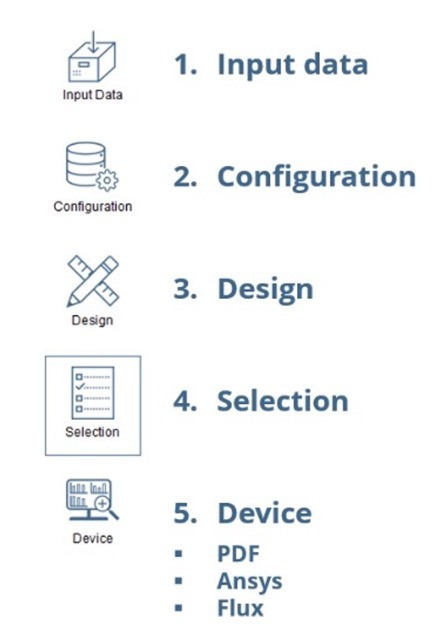
- Input data: Data input dialog. In this dialog the user can define and configure the voltage and current waveforms and the needed inductance or turns ratio for the
- Configuration: Design configuration dialog. In this dialog the user can define the databases to be used, the design restrictions and the models considered for the
- Design: Begin design In this dialog the design procedure begins, and results can be analyzed and compared graphically. Here the user can filter out the results to reduce the number of possible designs on the selection step.
- Generating at least one valid design enables the button for the 4th step (Selection).
- Selection: Device details and selection dialog. In this window the user can access the value of every parameter used in the design and can select a particular device for its comprehensive
- Selecting a design enables the button for the 5th step (Device).
- Device: Comprehensive analysis dialog. In this window the electrical and mechanical properties of the device can be seen, and it can be exported to third-party
You can design inductors, defined by their current and desired inductance and transformers, defined by the current and voltage on their primary side and their turns ratio. Both voltage and current can be defined by means of one of the generic waveforms defined inside SmartNetics (sinusoidal, triangular, or rectangular) or by loading a csv file.
In the current version, only E cores (or U cores, used in parallel to generate an E core) are considered. Regarding the materials, any material can be defined, including ferrites, nanocrystalline, amorphous and iron powder. On top of that, the user can select the conductor geometry, material and sleeve, and the insulators.
Regarding the core geometry, the user can enter any dimensions, even made-up ones, but is restricted to the use of E cores (or U cores, used in parallel to generate an E core).
For any other topic (core materials, conductors, insulators, etc.), the user can modify any entry of the database or add new ones.
The current version supports natural convection.
Capabilities planned in future upgrades during SmartNetics development will be addressed based on both collected user feedback and the difficulty of analytical resolution and implementation in the software.
Some of the main topics expected to be included in SmartNetics in future versions are:
- Waveform input:
- From harmonic content
- Trapezoidal
- Geometries:
- Cores with rectangular window: RM, Pot, PQ, ETD, …
- Toroids
- Winding strategies:
- Interleaving
- Upper-lower center leg winding
- Side leg windings
- Device types:
- Three-phase inductors with 3 columns
- Three-phase inductors with fourth column
- Single-phase multiple secondary transformers
- Three-phase transformers
- Electrical steel
- Databases:
- Databases editable from the application itself
- Thermal model:
- Dissipation by forced convection to air
- Databases for different media: air, oil, potting
- Temperature feedback to loss calculation (core loss)
- Device comparison and selection:
- Selection from table with organization (least to greatest or greatest to least) by columns.
- Device parameters:
- Parasitic capacity
- Export to third party tools:
- Finite Elements (such as FEMM)
- Electrical circuit simulation (such as PSIM or SIMBA)
- 3D CAD design tools
- Others:
- Effect of fringing flux on conductor losses
- Electrical isolation based on regulations
- B-H curve analysis
- Mechanical drawings
Simplified versions of windings for acceleration of FEM simulations